research topic(s): 3D printed concrete (3DPC), gyroid structure, 3DPC gyroid, concrete additive manufacturing
material: 3D printed concrete (3DPC)
location: Ithaca, NY
size: 6 - 500mm x 500mm x 500mm concrete gyroid cubes and 2 - 200mm x 900mm x 1800mm concrete gyroid walls
status: ongoing
principal investigator(s): Sasa Zivkovic, Director of the RCL, and Sriramya Duddukuri Nair, Director of Nairs's Research Group
research team: Moneeb Genedy, Caleb Lunsford, Onur Ozturk, Dan Shen, Lawson Spencer, and James Strait
fabrication team: Edie Blaze, John Conrad, Nikita Dolgopolov, Moneeb Genedy, Mark Krneta, Caleb Lunsford, Onur Ozturk, Pulani Tremel, Dan Shen, Lawson Spencer, and James Strait
funding provided by: Cornell Atkinson Center for Sustainability Academic Venture Fund and the College of Architecture, Art, and Planning at Cornell University
additional support: the Bovay Lab at the College of Civil and Environmental Engineering (CEE) at Cornell University and the College of Architecture, Art, and Planning (AAP) at Cornell University
journal article: { pdf }
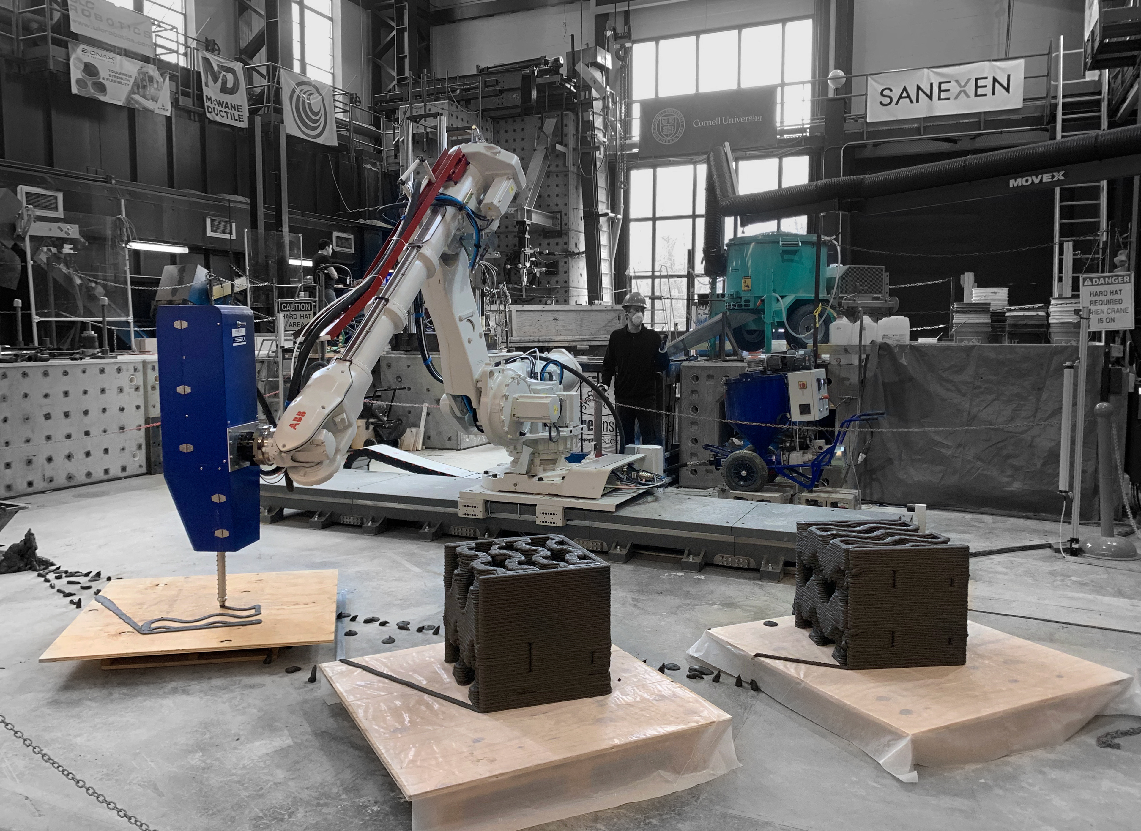
6-axis robotic arm extruding concrete with XtreeE end-effector
The gyroid is a triply periodic minimal surface (TPMS) that efficiently distributes stress under compressive loading in all Cartesian orientations. Despite the gyroid’s geometric ability to evenly distribute load, it has yet to be more broadly introduced to concrete additive manufacturing (AM) due to the difficulty of printing steep, doubly curved overhangs with a cementitious material. Consequently, the employment of the gyroid TPMS in AM has been limited to small and nano-scale applications. However, for doubly curved 3D printed concrete (3DPC) structures, the feasibility of the print is determined by the relationship between geometry, tool path design, and the mechanical and rheological properties of the concrete material being extruded. Using a 6-axis robotic arm with an accelerator-injection extruder as an end-effector, this research examines the fabrication limitations to construct a 3DPC gyroid. Finally, one of the overhang samples was prepared for a series of compression tests, which demonstrated that the 3DPC gyroid structure could support over 1000 kilonewtons. Though large variability was observed in the performance of the three gyroid samples tested, the research demonstrates that steep overhangs can be printed in concrete for gyroid-based structures.
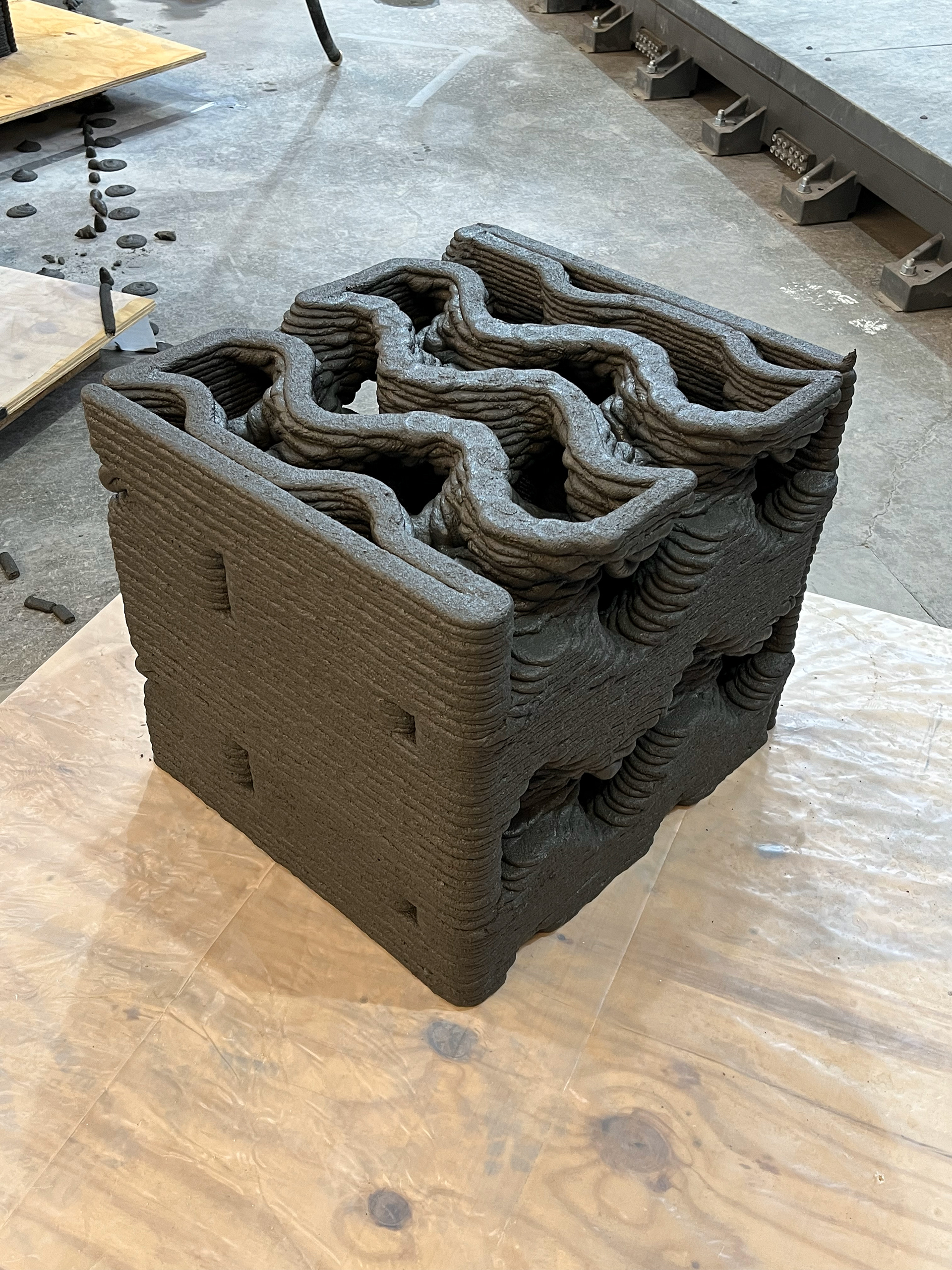
cantilever test of concrete gyroid cube | John Conrad
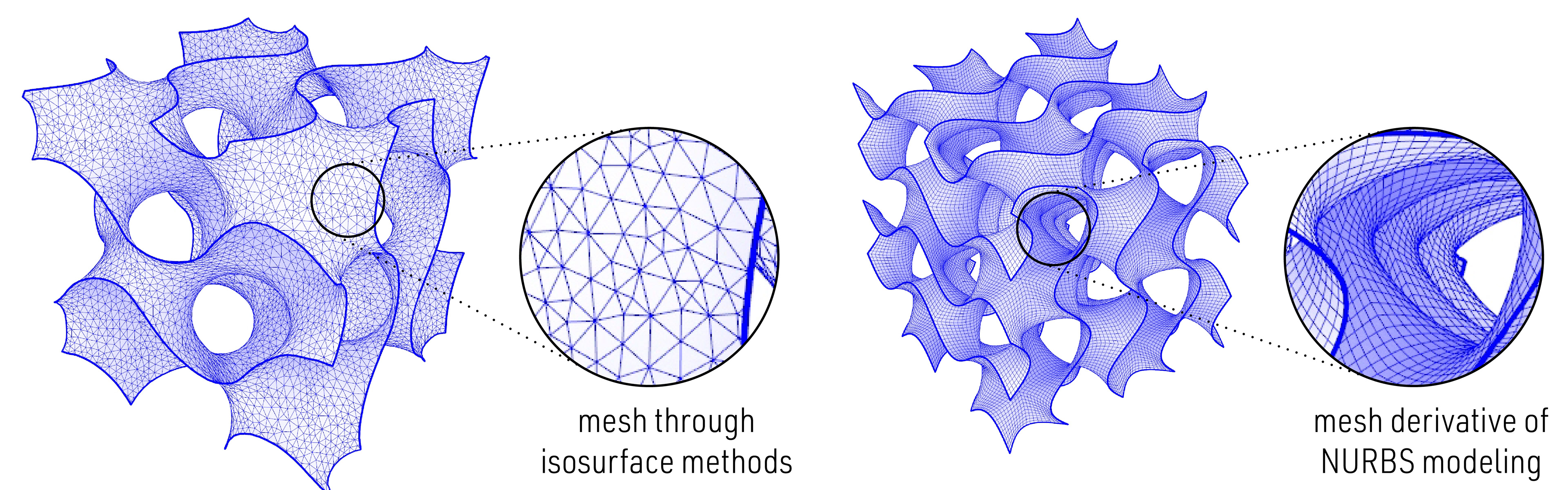
isosurface modeling method vs. NURBS modeling method of gyroid geometry
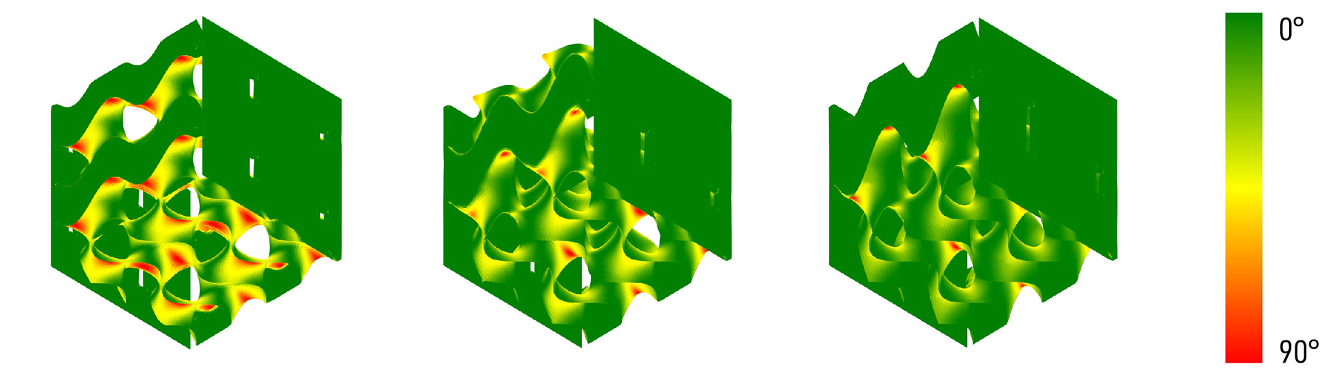
draft angle analysis for several overhang studies
Using a 2-component system with an in-house developed flowable mixture and with an injection accelerator at the nozzle's end to print larger overhangs. The following three concrete gyroid walls examine the influence of open and closed tool path designs. In an open tool path design, the nozzle’s printing direction reverses with every layer, thus changing the interlayer time gap along the length of the layer. On the other hand, a closed toolpath results in a similar interlayer time gap but leads to an increase in the total amount of material needed to close the tool path. In short, the start and end of each layer are adjacent in closed toolpath designs, but in open toolpath designs, the start and end are not immediately adjacent, forcing the tool to "circle" back on the subsequent layer.
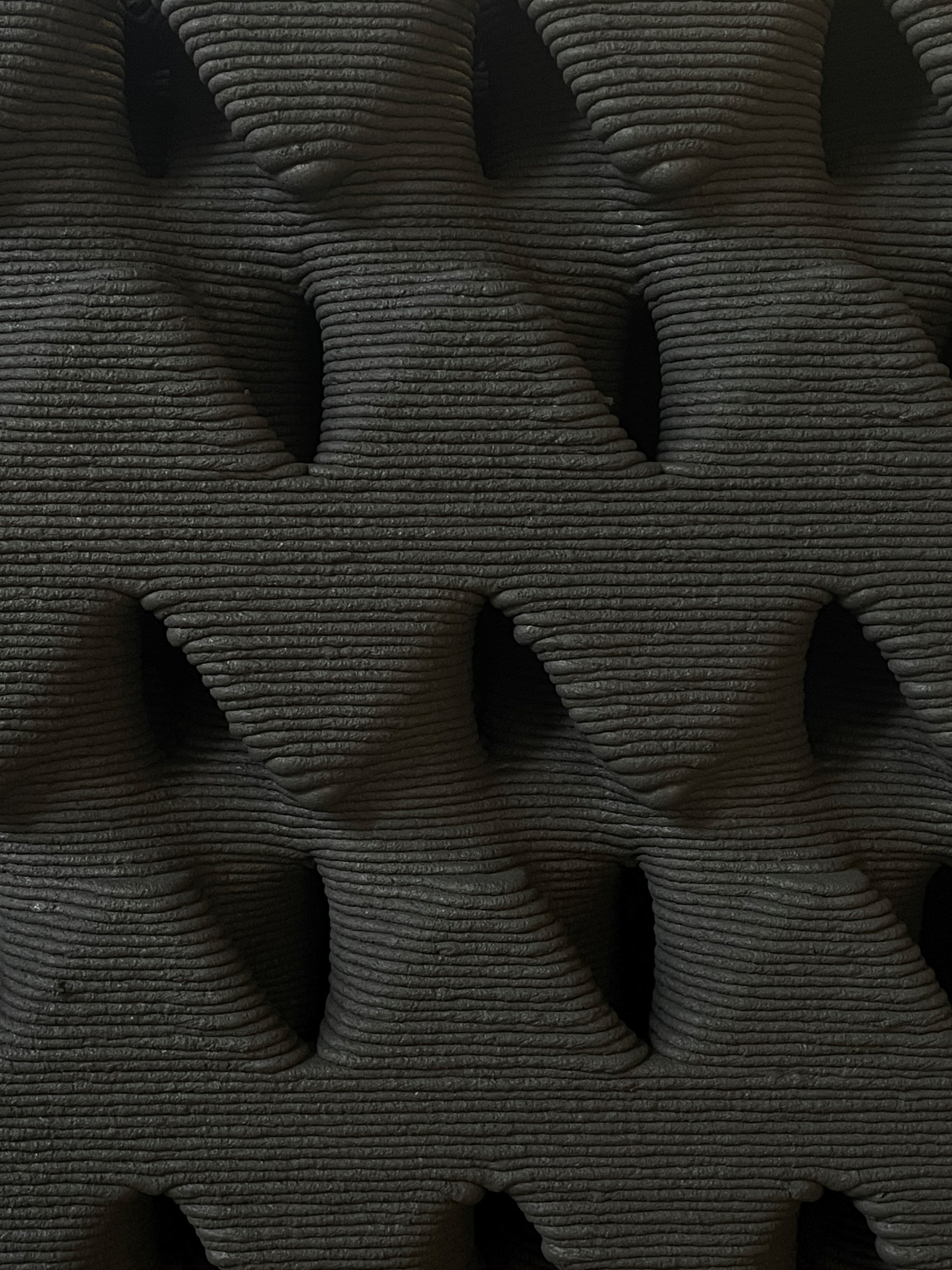
detail photo of concrete gyroid wall right after printing (wet)
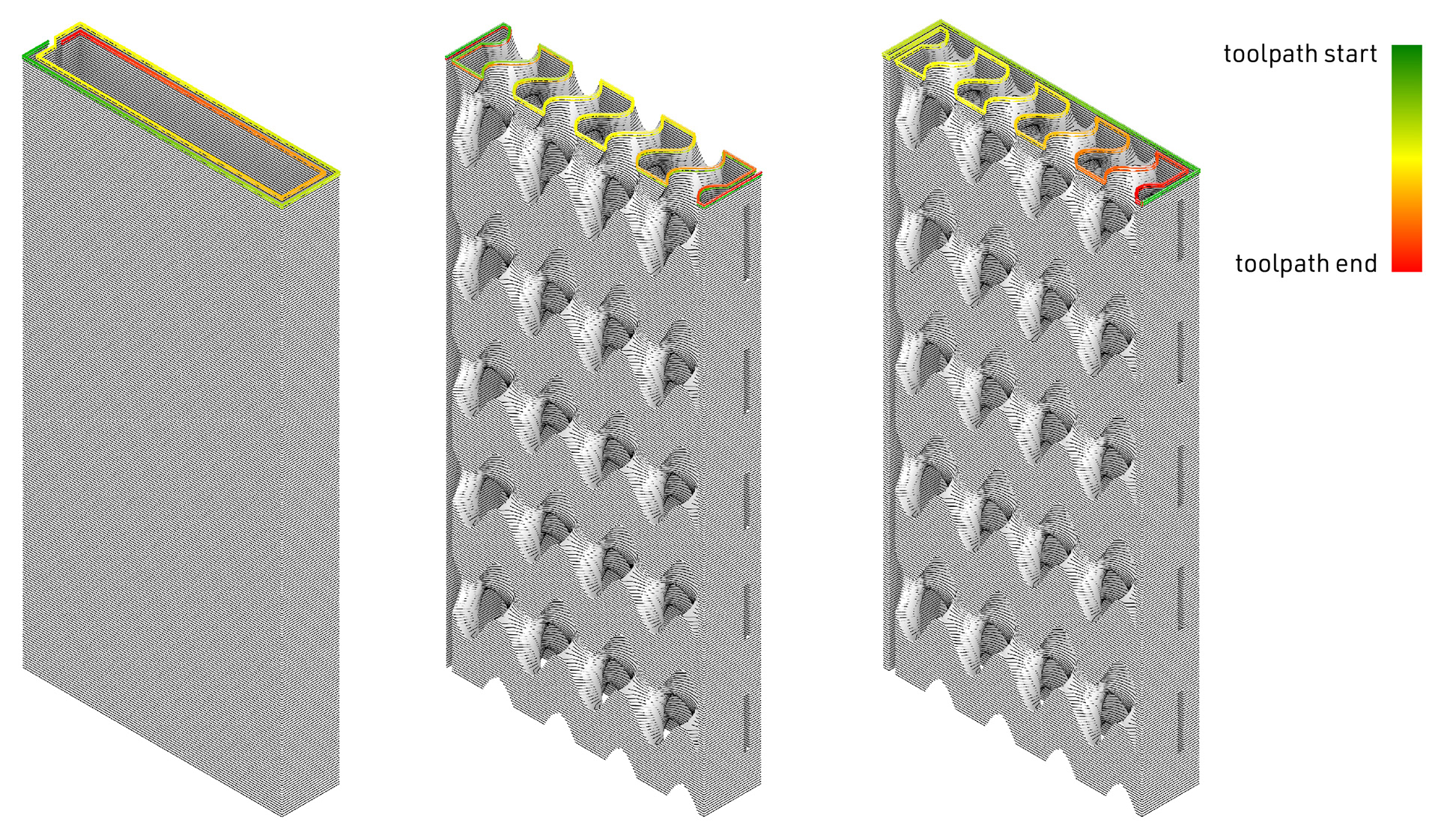
toolpath design for control wall (left), open toolpath gyroid wall (center), and closed toolpath gyroid wall (right)
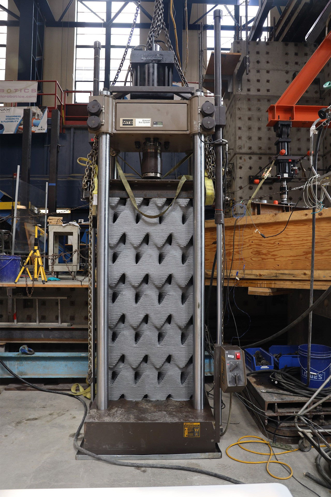
open toolpath gyroid wall before compression testing
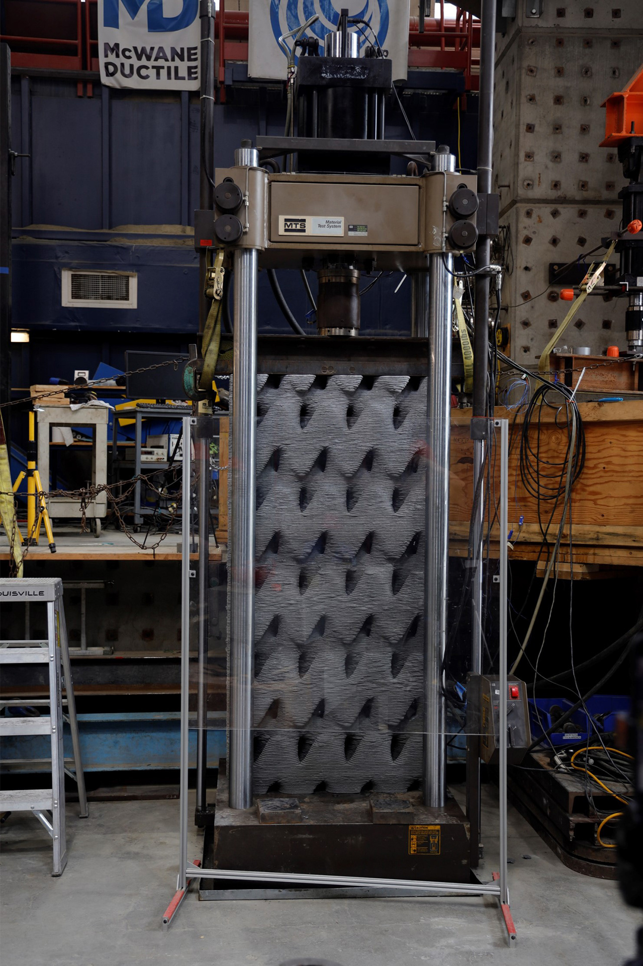
closed toolpath gyroid wall before compression testing